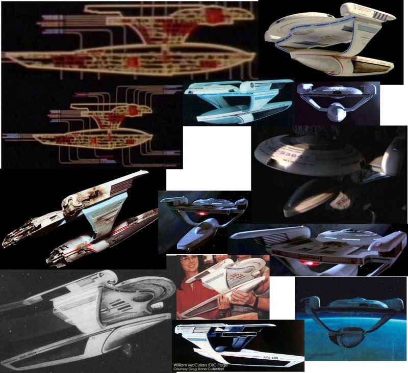
Ok, before I commit any time to this, I want to put out some feelers and see how much interest there is in cooking up some proper, accurate plans for the Oberth Class (and YES I am talking about the Grissom design, deal with it!) After a quick read through Bernd's Oberth scale article I can see that several of the problems he's highlighted stem from inaccurate schematics from both the encyclopaedia and the Fact Files. So what I'm after from you lot is any reference shots you can find of the miniature (particularly BTS shots) as after a good 30mins googleing, i can only find a handful of usable photos and most of them taken from the same angle. This will be ongoing, so I'll post my first WIP as soon as I can gauge what the level of interest is going to be. I know this sort of thing usually goes in the Design board, but I kinda want this to be more of a technical exercise than an artistic one.
Posted by Sean (Member # 2010) on :
It would be nice to get accurate schematics of the Oberth. I don't see why anyone would oppose your idea.
Posted by Reverend (Member # 335) on :
It's not opposition I'm concerned with, so much a as lack of interest.
Posted by Ritten (Member # 417) on :
Or interest and lack of time.
Posted by Masao (Member # 232) on :
Rev, as long as you're interested, that would seem reason enough.
Posted by Aban Rune (Member # 226) on :
I think I have a few good shots at home somewhere. I'll try and dig them up.
*whispers* what about deck plans for the antares?*
Posted by B.J. (Member # 858) on :
I'd like to see your take on the Oberth. It'll be interesting to see your solution to the whole pylon-turbolift issue.
Posted by Reverend (Member # 335) on :
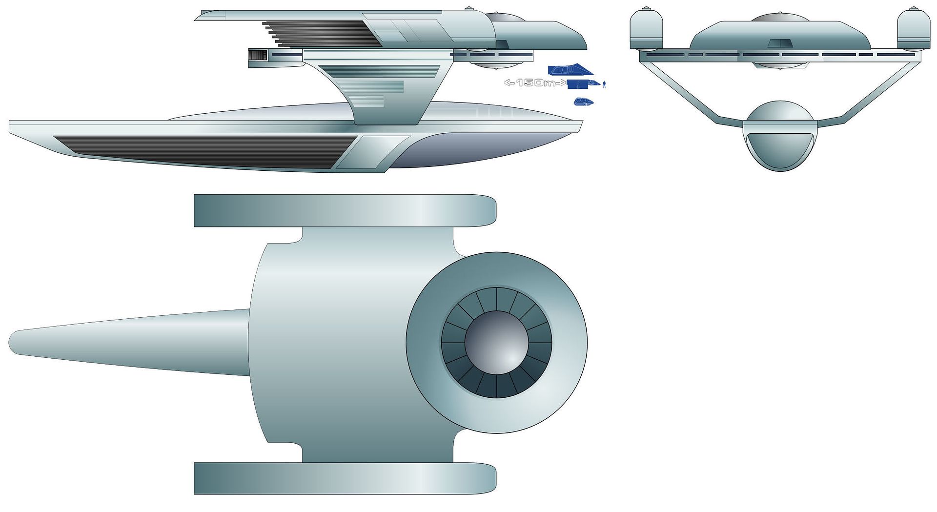
Ok, this is what I've got so far. ...and this is mostly what I'm going on.
Aban - In the words of the beardy bloke from Master & Commander (which I happen to have on in the background) "which it will be ready when it's ready". Plus I'm having enough trouble finishing off the Deneva deck plans and that thing only has 5 decks!
B.J. - The answer is much simpler than most think it is. Hard linked transporters. Job done.
Posted by Johnny (Member # 878) on :
Another shot of the Vico.
Somewhere I have a much bigger version.
And I know there are loads of photos of the proper Oberth model somewhere on flickr from when it was auctioned, but I can't find them now. Some were posted in another thread quite recently.
Posted by Sean (Member # 2010) on :
How big was the model used for the Vico? The same size as the original Grissom model?
Posted by Aban Rune (Member # 226) on :
The Vico schematics appear to show decks in the pylons.
Rev, I think you've already got all the photos I have, but I'll take a look.
Posted by Shik (Member # 343) on :
There was a top shot in a recent thread here, but I'm too lazy to look for it.
Posted by Johnny (Member # 878) on :
quote:Originally posted by Sean: How big was the model used for the Vico? The same size as the original Grissom model?
As I remember it, the model was not much more than two and a half feet long, so probably the same size as the one seen being held by the effects crew in that photo up there. I wouldn't be surprised if they just used a mold of the original model.
Posted by WizArtist II (Member # 1425) on :
Rev, somewhere I have some orthographic views of the model from ST3. It was part of a trading card set I think. I will try to find them in the next couple of days, scan them and post them.
Posted by Masao (Member # 232) on :
Card scans! Click me Posted by Reverend (Member # 335) on :
quote:Originally posted by Masao: Card scans! Click me
Those are EXTREMELY useful, cheers!
Posted by Masao (Member # 232) on :
My pleasure!
Posted by B.J. (Member # 858) on :
Interesting to see how *blue* the rest of the hull is compared to the saucer in those scans. They really bring out the hull plating pattern.
The scans also show something I've never noticed before - the back end of the ribbed part of the nacelles have an inward notch. I always thought that they were straight across.
Posted by Aban Rune (Member # 226) on :
Those shots are very cool.
So by my count, there are 4 decks in the bigger part of the saucer and 2 in the bulge on top. It also look slike there are rooms surrounding the bridge on deck 1. Seems to be 4 decks in the lower part too, not counting the top rounded part which seems to be deuterium storage or something.
Posted by Daniel Butler (Member # 1689) on :
The rooms surrounding the bridge would presumably be a conference room and captain's ready room or permutations thereof.
Posted by Shik (Member # 343) on :
Or senior officers' quarters.
Posted by Masao (Member # 232) on :
Ah, good a aft view! It's really hard to find any details on whatever that tail feature is. Oddly enough, in the Christie's auction photos that Starship Freak was kind enough to email, that bit has been blanked off.
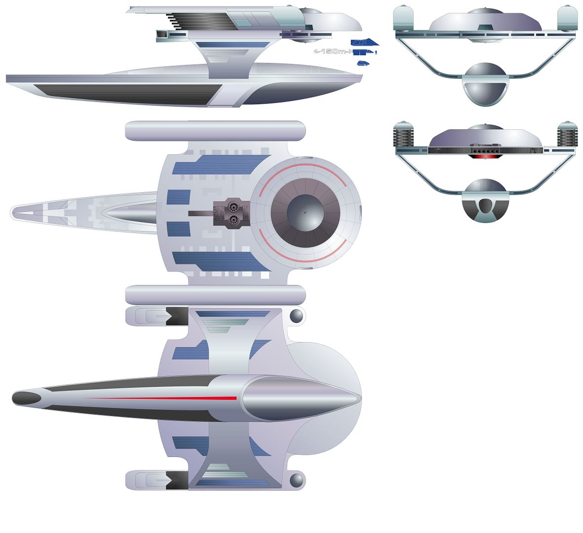
Anyway, here's the latest progress. Posted by Masao (Member # 232) on :
A few comments on contours, if it's not too early. 1. On the top and bottom views, the fronts of the nacelles should be more rounded. They appear to be half circles whose curves match the domes underneath. 2. The little fillet connecting the front of the nacelle to the primary hull dome should come out perpendicular to the nacelle. Yours start curving immediately towards the front of the ship. 3. The fillet appear to meet the primary at the rear edge of the door on the side of the primary hull. 4. On the bottom view, the curved line from the front of the pylon to forward of the center of the dish should begin to curve forward immediately. It does not have a straight perpendicular section as it leaves the nacelles. So, you've reversed the characteristics of the curves of the fillet and of this part. 5. The narrowest-appearing point of the fillet (mentioned in 3) is the point that it begins to curve forward. On your drawing, it's narrowest when it leaves the nacelle. This would be fixed by adusting the curves of the fillet and of the pylon.
This is why I hate drawing canon ships!
Posted by Masao (Member # 232) on :
6. The the cutout of the most-outboard pair of blue panels should have a sharp corner, not a curve as you've shown.
Posted by Reverend (Member # 335) on :
Bloody hell. If I ever manage to get this right, you are SO putting it in the Museum!
Posted by Masao (Member # 232) on :
Yeah those were my rough starting point, though you may notice it's missing the ventral sensor dome.
Posted by WizArtist II (Member # 1425) on :
I found my set, and Masao was too quick on the draw for me. I thought there were two other view but was wrong.
Posted by Reverend (Member # 335) on :
Ok, I think I've addressed all of Masao's points and noticed a few of my own. Still rather desperately need a clear view of the underside of the saucer substructure, especially the impulse engine's structure.
Posted by Shik (Member # 343) on :
The best you'll get is speculation, I think. You could see how might have the old SFSM vacuform model to look at. (I used a part of & tossed away the rest of mine years ago.)
Posted by Reverend (Member # 335) on :
I've already checked out some of the modelling sites and found this tutorial where the bloke states that the original mould is totally inaccurate and so scratch built his own one. Now he sights the Christie's auction and the DVDs as his reference source, but I can't get a clear view of it in ST:III and I've only seen two good photos from Christie's, so I have no idea what his source is. Perhaps I should get a hold of J�rg and see if he has any decent caps in that huge library of his.
Posted by Shik (Member # 343) on :
Oh, Pat Suwalski. Good gent.
Actually, his underplatform looks spot-on.
Posted by Aban Rune (Member # 226) on :
that is one dang cool model. And I do like the way he's done the underside. Makes sense to me.
Posted by Reverend (Member # 335) on :
Agreed, but as I said from the get go, I really want to use primary sources only rather than rely on someone else's interpretation. Perhaps I'll drop him a mail and see if he still has the reference shots he based that on.
Posted by Sean (Member # 2010) on :
Are there going to be deck plans accompianing this schematic?
Posted by Reverend (Member # 335) on :
We'll see. I've already roughed out a cross-section based on the 150m length, but it depends on how much energy I have left at the end.
Posted by Masao (Member # 232) on :
The new version is much better.
By the way, do you use blends or shaped gradients for fills are you only used circular or linear gradients. The top view of the nacelles could sure use a blended fill.
Posted by Reverend (Member # 335) on :
This is all done on a single layer in vector, so playing around blend ranges isn't much of an option. Even if it was I never could figure out how that worked anyway.
What I'll probably end up doing is add a separate object over the nacelle cap with a circular gradient and use the transparency along with the grid lines and details to hide the join.
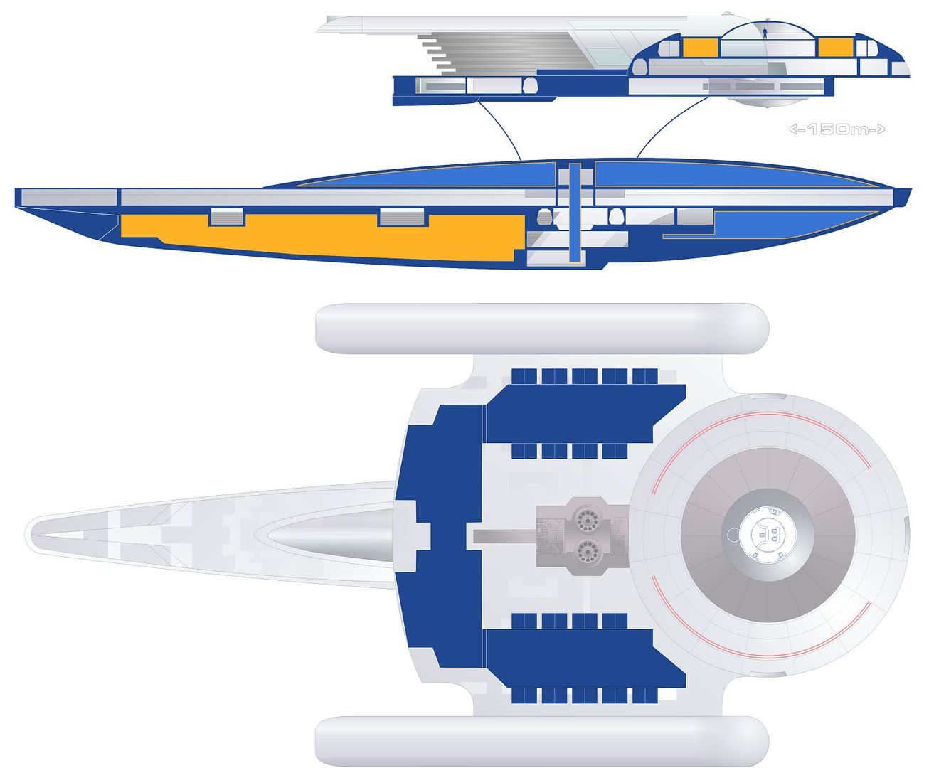
Anyway, here's that roughed out cross-section and a a basic layout of how I'm thinking the shuttle & cargo bays are arranged. Posted by Masao (Member # 232) on :
Creating blends is a vector tool, at least in Freehand. it allows you to merge two objects into a single object. it's very handy for shading sideviews of curved objects, line starship hulls. I use it all the time when circular, linear, or shaped graidents won't work.
Does your program have shaped gradients, which follow the outline of a shape?
Posted by Reverend (Member # 335) on :
Oh, you mean contour gradients. No I think freehand is about the only program that does that. I can only assume it renders the fill as a bitmap than applies it the the vector as an image tile, which would mean you have to re-render it if you make any changes to the polygon. Sounds useful though, perhaps there's a plugin that'd do it.
Posted by Masao (Member # 232) on :
Contour gradients (what I called shaped graidents) work just like circular or linear gradients. You can change the shape or the colors or whatever just as with other gradients. As far as I know, no bitmaps are involved.
Blending is when the program draws a designated number of intermediates between two objects/shapes. Both the color and shape are dealt with. Again, it's completely a vector thing. I'm pretty sure other programs can do it too because I've seen it used by non-Freehand schematic artists.
Posted by Reverend (Member # 335) on :
I've had a quick google and can't find any mention of it in relation to PSP, so I'm stuck with my method I think.
Posted by Masao (Member # 232) on :
Here's a demostration of fills and blends Freehand can do. I expect that Illustrator can do similar things.
I'm still learning how to use blends correctly, but you can do shading that would otherwise require a pixel editor.
Posted by Reverend (Member # 335) on :
Yeah I just had a quick play with the "object blend" function on Illustrator. I can really see the potential, but it's not enough to make me jump ship onto to Adobe quite yet...though if Corel continues to butcher PSP like they did with version XI then I have have to sooner or later. Still, I have plenty of experience cheating light and depth, so I'll just have to muddle along.
Posted by Masao (Member # 232) on :
Freehand was purchased by Adobe, so will probably be phased out eventually in favor of Illustrator. That's life!
The blend tool is very, very useful. Sure the appearance of a blend can be approximated by a combination of objects with various gradients, but using a blend tool is so much easier.
Posted by Aban Rune (Member # 226) on :
Very nice deck plans so far. What bridge have you stuck in there? Is it the Grissom's or something you made?
Posted by AndrewR (Member # 44) on :
quote:Originally posted by Reverend: Anyway, here's that roughed out cross-section and a a basic layout of how I'm thinking the shuttle & cargo bays are arranged.
At the back of the rectangular section that is behind the 'saucer' - where the impulse engine is... along that back edge looks like overlapping, sliding doors. I reckon prime place for cargo doors, rather than shuttlebay doors - seeing as there are already 'shuttlebay'-looking doors around the saucer rim.
Posted by AndrewR (Member # 44) on :
quote:Originally posted by Reverend: Ok, I think I've addressed all of Masao's points and noticed a few of my own. Still rather desperately need a clear view of the underside of the saucer substructure, especially the impulse engine's structure.
Any possibility you could include a runabout for size comparison? It's one of the best people-ship size comparisons we've had on screen.
Posted by Reverend (Member # 335) on :
quote:Originally posted by Masao: Freehand was purchased by Adobe, so will probably be phased out eventually in favor of Illustrator. That's life!
The blend tool is very, very useful. Sure the appearance of a blend can be approximated by a combination of objects with various gradients, but using a blend tool is so much easier.
Tell me about it! I'm still using PSP X because 5 mins using XI told me Corel had completely fudged it or sacked most of the old Jasc people that were probably still around when PSP X was made. I've always had difficulty finding my way around Photoshop and Illustrator (compounded in the latest version by ultra low contrast menus) and there's nothing more irritating than not being able to use the keyboard shortcuts for vector node editing that I've been habitually using for years.
quote:Originally posted by Aban Rune: Very nice deck plans so far. What bridge have you stuck in there? Is it the Grissom's or something you made?
It's the TMP Enterprise that I rearranged based on the one or two screen caps I could find. I'm almost certain the Fact Files did one of their 3D illustrations for Grissom, but for some reason nobody seams to have scanned it.
quote:Originally posted by AndrewR:
quote:Originally posted by Reverend: Anyway, here's that roughed out cross-section and a a basic layout of how I'm thinking the shuttle & cargo bays are arranged.
At the back of the rectangular section that is behind the 'saucer' - where the impulse engine is... along that back edge looks like overlapping, sliding doors. I reckon prime place for cargo doors, rather than shuttlebay doors - seeing as there are already 'shuttlebay'-looking doors around the saucer rim.
Yeah, as you can see on the dorsal plan that's where I have the main cargobay access. I'm not convinced by having the shuttles in the saucer, as it doesn't make sense to me to crowd an already crowded primary hull. At the moment I have them down as either docking ports and/or airlock to smaller cargo bays. Just more evidence that the model builder thought this was going to be much bigger than it was portrayed.
Posted by Aban Rune (Member # 226) on :
I'm pretty sure FF made a grissom illustration too. I remember thinking there were way too few stations on the thing.
Posted by Jason Abbadon (Member # 882) on :
Is that the studio model, though?
Posted by Peregrinus (Member # 504) on :
quote:Originally posted by Reverend:
quote:Originally posted by Aban Rune: Very nice deck plans so far. What bridge have you stuck in there? Is it the Grissom's or something you made?
It's the TMP Enterprise that I rearranged based on the one or two screen caps I could find. I'm almost certain the Fact Files did one of their 3D illustrations for Grissom, but for some reason nobody seams to have scanned it.
Um, if you Google "grissom bridge", this is one of the first results that comes up...
--Jonah
Posted by Reverend (Member # 335) on :
Weird, I must have tried half a dozen googles trying to find it before.
As for the reference photos, while the model is well made it doesn't look like the filming miniature and I'm determined to stick to primary data sources so I'd rather see the reference they used to make that model.
Posted by Captain Serek (Member # 1038) on :
The Grissom bridge drawing from the Fact Files/Magazine is very familiar. Good luck on this project.
Posted by Jason Abbadon (Member # 882) on :
quote:Originally posted by Reverend: Weird, I must have tried half a dozen googles trying to find it before.
As for the reference photos, while the model is well made it doesn't look like the filming miniature and I'm determined to stick to primary data sources so I'd rather see the reference they used to make that model.
It's probably as close to the filming model as possible- Thomas sasser is the guy with seemingly-unlimited access to Paramount's shooting models (pre-auction, obviously). He's the guy that mastered Polar Light's (incredible) 1:350th Enterprise kit, the TOS E and Klingon kits and has the blessing of Paramount.
Seriously- the guy's a detail and accuracy enthusiast: I'd bet real cash that his model is prop accurate.
All the Oberth toys, models and minis have all or most of the details of that model as well (Micromachines, Futara, FASA mini, SFSM styrene kit, Osyssey Slipways and Starcrafts resin kits, etc.)
Posted by Reverend (Member # 335) on :
Quick update to the deck layout. May be some more soon.
Posted by The Mighty Monkey of Mim (Member # 646) on :
You've probably already thought of this, but if you still need better shots of the filming model, you could ask Doug Drexler if he's got any that he could post on his blog...
Posted by Reverend (Member # 335) on :
I have been following his blog and I'm sure if he has anything good he'll get around to it eventually. No sense in imposing on generosity.
Posted by Nim (Member # 205) on :
Out of curiosity: I think the Oberth's saucer and nacelles are nice, has anyone ever made a successful kitbash of the Oberth, using only the nacelles and saucer to build a "Constitutionized" Oberth?
Posted by B.J. (Member # 858) on :
I think I'd have the bridge half-sunk into the next deck, if only to avoid having a funky-shaped turbolift tube and car.
Posted by Reverend (Member # 335) on :
Nim: I have seen various kitbashes of the Oberth and nothing I've seen looks even remotely as good as the original. The design is practically sculpted so a kitbash really doesn't work. B.J.: Way ahead of you.
Posted by Jason Abbadon (Member # 882) on :
Nim, the nacelles from a Connie Refit look insanely too large for that saucer if connected at the same place. That being said, the Oberth primary hull lends itself to many variants- one with a Miranda torpedo pod instead of the secondary hull, one in a Ptolemy configuration, etc.
A million years ago I made a hospital variant:
I think the ILM guys intended the Oberth's nacelles to the the next step forward in warpdrive- the Excelsior test models have something very close. I can invision some hybrid between the Oberth and Excelsior nacelle...might be cool.
Posted by Reverend (Member # 335) on :
For the purposes of this thread, I'm sticking with the theory that it's a design with a heavy Vulcan influence, circa 2185.
As for the kitbash, nothing against the modelling itself, but the design is hideous. Oberths are better left unbashed, just as Buddha and ILM intended.
Posted by Jason Abbadon (Member # 882) on :
Yeah, it's not much of a design- the secondary hull is a super-glue tube with greebles and it's from waaaay back but the point I was trying out is that the Oberth primary hull can be used for stuff other than scientific research and possibly can serve as a multirole vessel for non-combat missions. I tried to make it obvious that the ship seperates (thus the two colors of hull).
If nothing else, the primary hull, freed from that science pod would be a fine courier/transport for diplomats and other VIP's. beats shooting them off in a torpedo casing anyway...
Posted by Reverend (Member # 335) on :
A little bit of progress:- Just a roughed out plan based on the idea that the bridge with the airlock seen in "Naked Next Thursday Teatime" was in fact on deck 10 (above the deflector and below the fuel tanks.)
Posted by Nim (Member # 205) on :
Jase:
quote:Nim, the nacelles from a Connie Refit look insanely too large for that saucer if connected at the same place.
I didn't imply adding Constitution-nacelles to the Oberth saucer, I meant liberating the Oberth nacelles and saucer (from the large bottom plate) and putting them on a new cylindrical engineering section that's -say- twice the length of the saucer (though not that thing that is slung under it in ST-III), with appropriate pylons and neck.
So that it would be, essentially, a connie/Excelsior-shaped ship, but 100 meters long. It's just an exercise in aesthetics.
But fine, if it hasn't been done I'll have to do it myself, good day sir. .. I said GOOD DAY sir!
Reverend: Which deck holds the torpedo launcher? Haven't read up on the class.
Posted by Reverend (Member # 335) on :
Deck 11 or 12 I think. I'm going with the idea that the dark aperture on the tail end of the secondary hull is the probe launcher, rather than another sensor array as some seam to label it.
Posted by Nim (Member # 205) on :
Cool. I've been looking at that obscured hole on schematics, wondering why the creators put it there and what the function was, as it already has an impulse engine. Does the Oberth have a proven deflector?
Also, to clarify my earlier posts, here's a very rough and simple but straightforward idea of my take on a Oberth-kitbash (taking obscene liberties with Reverend's graphic). I could do better with 3d software.
Posted by Reverend (Member # 335) on :
Well it's function was a place to hide the rear mounting point for the motion control rig, I'm just supposing it's a probe launcher on the theory that 1)There aren't many other candidates for a launcher and 2) The ship has enough sensor arrays as it is - an aft facing long range array is overkill. After all, why would you want to scan a sector you just left? Dropping a probe relay makes more sense if long term observations are required.
As for the deflector, it's pretty clear on the MSD that it's under that silver coloured cowl, though I don't see it as looking like a normal dish or blue glowy thing. I envision it as a chaotic mass of split concentric cylinders, with various spikes and antennae, taking up as much of the interior volume as possible.